There are many reasons to consider replacing a sprayer boom with a recirculating boom. Wilger manufactures many components that ease the transition to recirculating sprayer booms, or parts to engineer a top notch sprayer boom from scratch. Since there are a variety of configurations for a recirculating sprayer boom, ensure to familiarize yourself to make the most of your system.
SCOPE of work: This would be if your sprayer boom is currently conventionally plumbed by section, and you have some means to turn off nozzles remotely in the cab during recirculating mode (e.g. PWM system, air-off nozzle control, etc). The walkthrough will ONLY address how the plumbing on the boom would change, not the feed lines/return lines as there are a number of ways to vary feed. Perhaps consult the ‘recirculating boom guide’ at Sprayers 101 (https://sprayers101.com/recirculating-boom/) for some insight.
STEP 1: Decide on plumbing orientation for flow inflow and recirc outflow.
Example configurations:
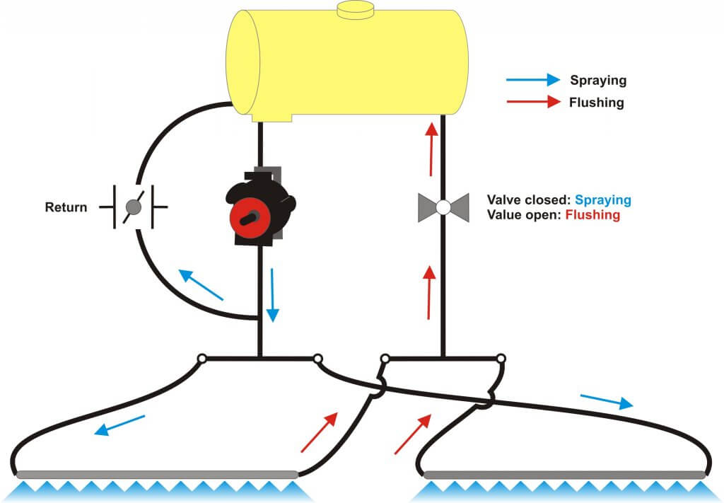
“Outside IN”: Plumb main boom feeds to feed from both outside wings (or breakaway sections), with the recirculating outflow leading back from a common center-rack outflow.
“Inside OUT”: Plumb two feeds from center rack to supply right boom and left boom, with the outflow of the sprayer boom continuing from the right and left outside boom connecting back to a single outflow when the meet at the center rack.
Recirc Tube versus Hose Option: Regardless of orientation, you might also choose to replace the plumbing hoses on the sections with unpunched stainless steel tubing to have less plumbing weight (compared to 1-1/4″ rubber hose), as well as maintain easier to maintain sprayer booms for chemical buildup.
STEP 2: Cross-reference Nozzle outlets on each section to Wilger boom pipe part #, ensuring the ends are coordinated to fit properly with actual spacing.
Since recirculating booms require consistent nozzle spacing to be kept, boom ends can be as short as possible to minimize sharp elbow fittings and boom frame interference. This means any connectors could be 90°/45°/Straight hose barb fittings with ~2″ ends. For very long tube sections, (e.g. more than 11-nozzle tubes/pipes) expect to have those sections plumbed by multiple tubes with a 2″ end/10″ end to ensure 20″ spacing it kept between ‘tube to tube’ connections.
PRO TIP: If spray boom tubes are being shipped, it is common to try keep tubes shorter than 11′ to avoid ‘extra long package’ charges from some carriers/shipping companies.
An 120′ on 20″ spacing (~36m on 50cm) example layout might be similar to this (from left break-away section to right breakaway):
LEFT Breakaway: 5 outlet – sidefed – This would be a 5-Outlet tube with 2″ ends.
LEFT Secondary Wing: 11 outlet – sidefed- This could be an 11 outlet single tube, with 2″ ends.
LEFT Primary Wing: 16 outlet – sidefed – Given this tube’s length, it would likely be split into 2x 8-outlet tubes, with 2″ and 10″ ends. (The 10″ end would be the tube to tube connection)
Center Rack: 8 outlet – sidefed- This would likely end up as a 4-Outlet & 4-Outlet tubes with 2″/2″ ends. This would allow for the two tubes to have a 90° elbow that feeds back to the tank (or is fed from pump, depending on chosen orientation).
RIGHT Primary Wing: 16 outlet – sidefed- Given this tube’s length, it would likely be split into 2x 8-outlet tubes, with 2″ and 10″ ends. (The 10″ end would be the tube to tube connection)
RIGHT Secondary Wing: 11 outlet – sidefed- This could be an 11 outlet single tube, with 2″ ends. Alternatively, it could be something like an 8-outlet tube with 2″ end/10″ end as well as a 3-outlet with 2″/10″ end. The benefit for a 8+3 tube situation is reducing the shipping length to the minimum acceptable size, and having common tube parts.
RIGHT Breakaway: 5 outlet – sidefed – This would be a 5-Outlet tube with 2″ ends.
Total of 72 outlets
With this, we can breakdown a parts list:
2x 5-Outlet 2″/2″ ends
2x 11-Outlet with 2″/2″ ends
2x 4-Outlet with 2″/2″ ends
4x 8-Outlet with 2″/10″ ends
Total tubes: 10 tubes
STEP 3: Compile Plumbing Connection Parts List
Depending on the style of fittings that are used (Quick-Nut fittings, or the newer Quick-Flange fittings), a variety of fittings would be required. In premise, these fittings will follow a similar format:
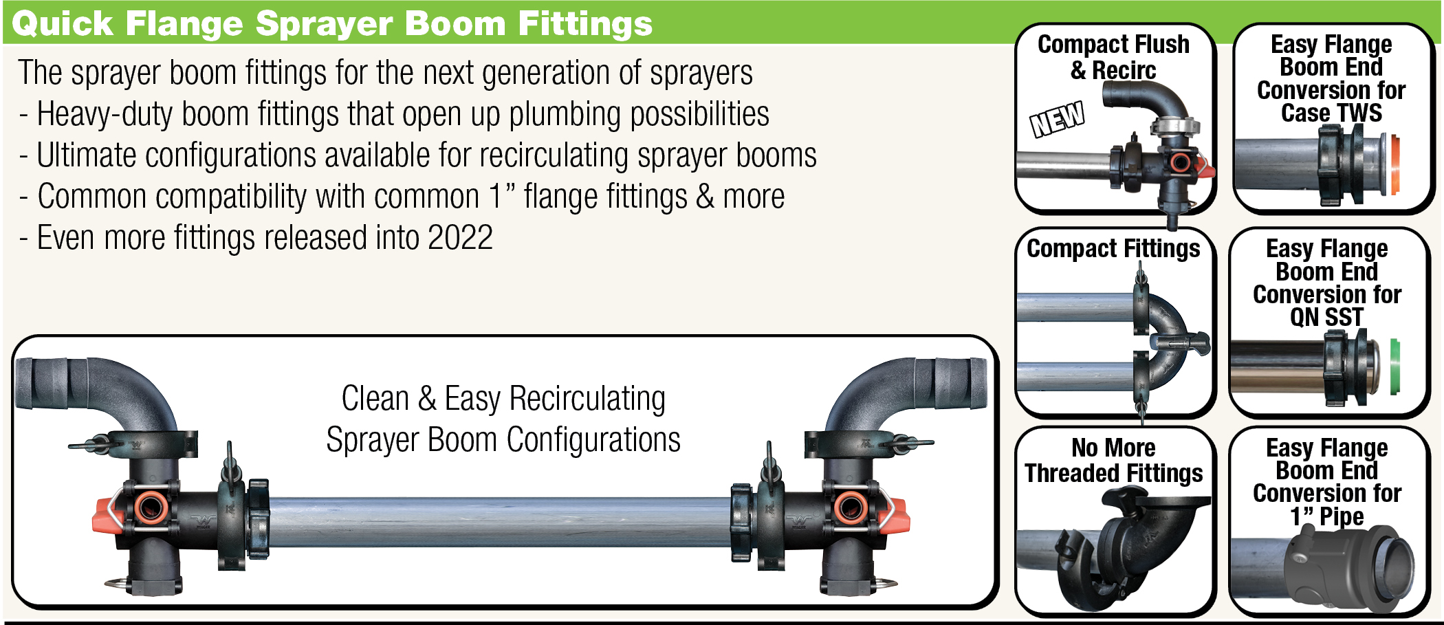
For new recirculating sprayer boom kits, we would recommend using Quick-Flange parts, as parts have been designed and manufactured specifically to optimize recirculating sprayer booms. (e.g. COMBO-RATE Boom End Flush Valves, etc.)
For Quick-Nut Fittings (QN100)
For any side-fed 2″/2″-end pipes (per pipe):
2x QN100 Male Pipe End Adapters (#25171-00)
2x QN100 Connection O-ring Seals (#25160-02)
2x QN100 Hose Barb or other feed fitting (e.g. 1-1/4″ 90° Hosebarb #25161-01)
2x QN100 Nut for each hose barb fitting or endcap, to bind the fitting to the Pipe-End Adapter (#25160-03)
For any PAIR of side-fed 2″/10″-end pipes (per PAIR of pipes):
3x QN100 Male Pipe End Adapters (#25171-00) – 2x for capped end, 1 for tube to tube connection.
1x QN100 Female Pipe End Adapter (#25170-00 two-piece assembly) – For Tube to tube connection
3x QN100 O-ring Seals (#25160-02)
2x QN100 Hosebarb Outlets (#25161-01 for 90° 1-1/4″ elbow on either side)
2x QN100 Nuts (#25160-03 for connecting hosebarb fittings to pipe end adapters)
For Quick-Flange Fittings (QF100)
For any side-fed 2″/2″-end pipes (per pipe):
2x Flange End Adapters (#27312-00)
2x 1″ SST Pipe to QF100 Seals (#27315-00)
2x QF100 Quick Clamp (#27310-00)
1x QF100 Hose Barb or other feed fitting (e.g. 1-1/4″ 90° Hosebarb #27343-00)
1x QF100 End Cap (#27353-00) or Boom End Flush Valve Assembly
For any PAIR of side-fed 2″/10″-end pipes (per pair of pipes):
4x QF100 Male Pipe End Adapters (#27312-00)
1x QF100 SST tube to SST tube gasket seal (#27318-00)
2x QF100 SST to Flange Gasket Seal (#27315-00)
3x QF100 Clamp (#27310-00)
2x QF100 Hose Barb or other feed fitting (eg. 1-1/4″ 90° Hosebarb #27343-00)


