EFM TABLET SELECTION
Having a working tablet is just as important as having the EFM system set up correctly. Improper tablets or poor performing tablets can often be the root cause of many troubleshooting calls and issues, so to provide some explanation of what a ‘proper’ Android tablet would be:
Leading into this, there are over 30,000 android tablets that are ‘compatible’ with the EFM app, but tablet manufacturers do not make it very easy to tell actual differences in performance, or custom operating systems that are used on the tablet. So, this means we can give a general rule of which android tablet brands should be chosen, or what aspects of tablets should be avoided:
Suggested Tablet Brands:
Most brand-name tablets that are recognizable (Samsung, Acer, etc.)
Examples: Samsung Tab S9 or S10, Acer Iconia Tab P10 or P11
Tablet Brands/Types or Models to Avoid: (Often due to custom operating systems that are trimmed down or missing core functions, or have cheap WIFI hardware that will lead to poor performance or connectivity)
1. DO NOT USE Tablets with ‘LITE‘, ‘KIDS‘, or ‘+‘ in the name (Generally these tablets will be running a custom Android operating system, and often do NOT show that they are limited function tablets, not suitable for commercial use). For example: Avoid Samsung Tab S6 LITE, Samsung Tab A9+
2. DO NOT USE Phones are generally not to be used as they will also have mobile data being used, which can interfere with the sole WIFI function of the app. While phones can be used in airplane mode with WIFI on only to test systems or troubleshoot, it is recommended to use a tablet only.
3. DO NOT USE Amazon FIRE tablets – These tablets are a limited use tablet and not intended for commercial use. They are similar to a tablet with a custom operating system and trimmed down components that are not suitable for sustained commercial use. Often the apps will simply crash due to missing system components.
4. DO NOT USE very low-cost brands of tablets. Generally these tablets are very cheap (<$150), and have brand names that are unknown or not common at all. Sometimes these tablets have names or models that mimic a mainstream tablet, but are running non-standard or lacking hardware. (For example Linola Tab M9, UROA brand of tablets, ULTITAB, UNISOC, BLACKVIEW, BYYBUO, WPAD, TOPSAND, WEELIKEIT, ZTE, UMDIGI). Unfortunately, these non-branded or knock-off tablets are not suitable due to a variety of reasons. While they may work functionally somewhat, it is recommended not to use them as there will be software incompatibilities.
1.The app (requires Android OS 10.0+) will request to ‘trust’ the WIFI connection (when using the app). All permissions must be granted to the app for proper function.
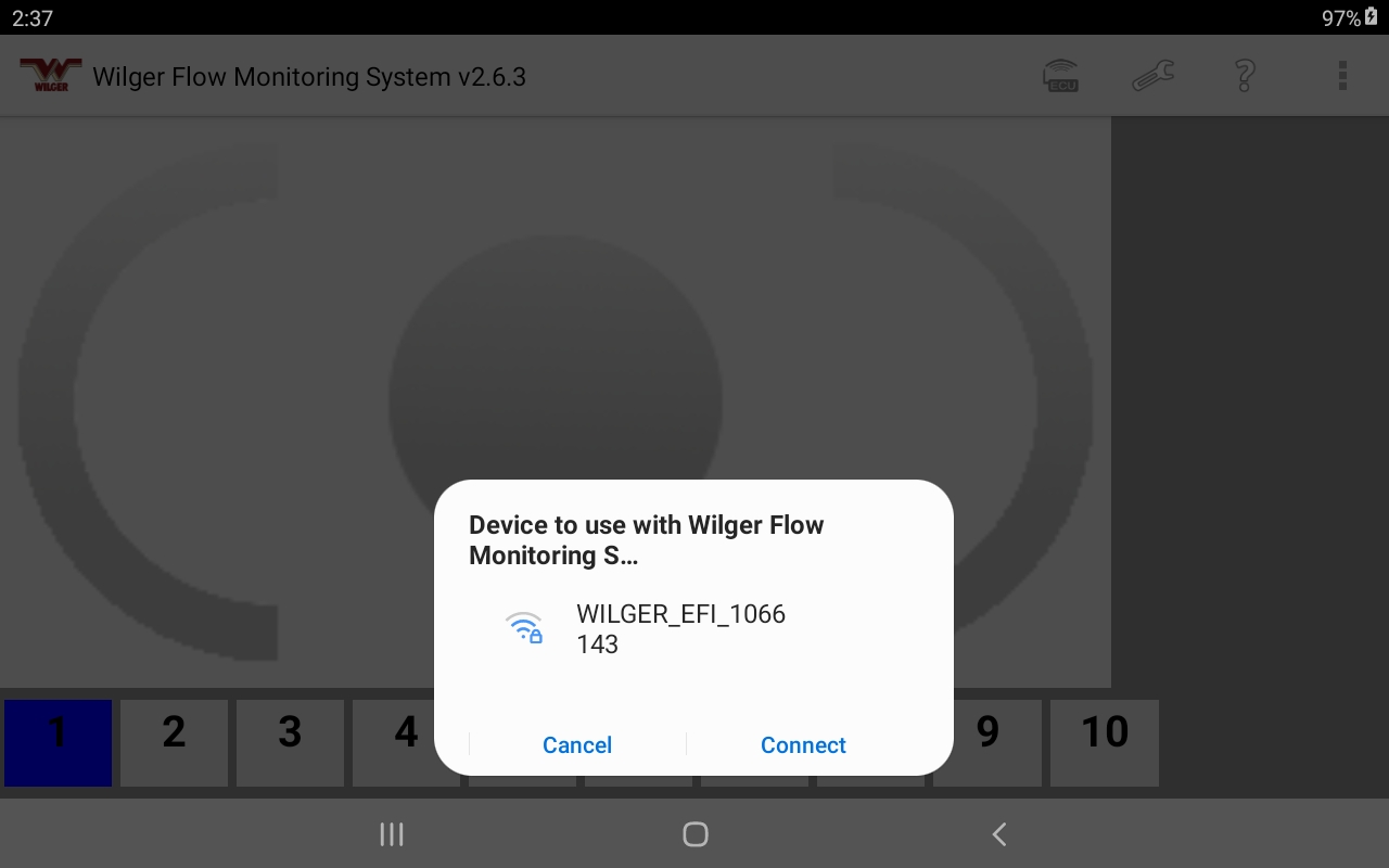
2. The EFM System WIFI can now be connected to via the Tablet’s SETTINGS -> WIFI page. Simply select the WILGER_EFI_####### network, and use the password that is IDENTICAL to the network name. E.g. For connecting to ECU serial #1234567, you will see ‘WILGER_EFI_1234567’ broadcasting. Select that WIFI network, and enter the password WILGER_EFI_1234567 .
2.The app/tablet seems to ‘crash’ before anything can be used within the app. Often this is an occurence for older tablets, or more often tablets that are of a questionable manufacturer or a manufacturer using a non-standard version of ANDROID operating systems (non-branded tablets, Amazon fire are the key culprits).
As a troubleshooting method, it might be advisable to download a legacy version of the app and test that for use. The LEGACY versions of the app are located in the DOWNLOADS section of the website, within the EFM SYSTEM tab. These versions are not updated, and are used at your own risk for troubleshooting purposes.
With a multitude of different systems, implements, and other factors, it can be a common situation that something might be conflicting with or not set up properly. This page is designed to be an informal check list of problems that have been documents or resolved from customer troubleshooting. If you have any issues (be it critical or not), you can by all means report an error or trick to fixing something that might help the next user.
ECU Connectivity Issues & Observations
With the ECU, it requires a 12V power supply, with the correct connection for Positive/Ground wire connection. The tolerance for voltage is 10.8-13.8V. Any voltage lower than the minimum will often cause the ECU to not complete the power/connection cycle. Voltage over 13.8v can also conflict with proper set up.
If there was a situation where the in-cable fuse has been flipped unknowingly, the fuse box must be opened and reset. The fuse box is located on the battery harness cable that is supplied with the ECU kit (20603-00 kit).
In a situation where a sensor cable, or harness connection wire has been damaged, there may be power/electricity running through the sensor feedback cables, causing a fault. Often this can still result in the ECU powering up properly, but the sensor feedback not showing properly and having multiple dead sensors on screen (or all sensors).
-
- Ensure you check all connectors for bent pins, residue, liquid, debris, or anything that could interfere with proper connection, or cause electrical fault.
If this is suspected, a simple test is to unplug the ECU at the 8-pin connection that would go to the nodes. If the ECU condition is restored to working functionally, it can be surmised there is a short down the length of the nodes.
Proper steps to isolate shorts:
- Unplug ECU from all NODES. (Remove 8-pin connection. Leaving the POWER/Battery cable attached to the ECU). Check ECU operation on both POWER/WIFI light, as well as in android app if connectivity has been restored.
- Plug in 1st node to ECU. Disconnect 1st node from the next node. Check ECU/App operation. If all balls/sensors in app show properly. Carry on to next node.
- Plug in next node in series, disconnecting the next node in series. Check ECU/app operation. If all balls/sensors in app show properly. Repeat step 3 until you find a node that causes the ECU/app operation to fail.
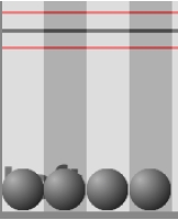
- Failure of the app would typically mean previously red balls/sensors in the app would turn GREY in color, signifying they are offline.
- Once a node is found to be a culprit with potential short, unplug all quad-sensor cables from the node divider harnesses (labeled A/B/C/D), and verify if ECU/app operation improves. Expect that the quad-sensor cables on that node will be grey, as they are offline.
- If app operation is functional without the quad-sensor cables connected, the node should be OK.
- Connect each quad-sensor cable divider (A/B/C/D) one at a time, ensuring that the previously grey sensors are now powered up and RED.
- Continue to connect quad-sensor cables until one is found to cause functional issue in the system. Once the quad-sensor cable is isolated as damaged, it should be checked or replaced if the damage is found.
- If the sensor connection has been compromised or damaged, it may require replacement and cleaning inside the flowmeter body to ensure future damage is avoided.
With the initial powerup of an ECU that has not yet had any connection to an Android tablet application, the ECU will cycle on 10 second intervals. It is NORMAL and functioning if the ECU power light stays solid for 10 seconds, with WIFI light blinking consistently, followed by both POWER/WIFI light turning off, and restarting the cycle.
POWER: SOLID RED // WIFI: BLINKING RED
30 Seconds, restart cycle until connection is verified.
Once an ECU has connected to a tablet app, it will shift this cycle to 30 seconds. (Power solid for 30 seconds. WIFI blinking for 30 seconds. Reset cycle)
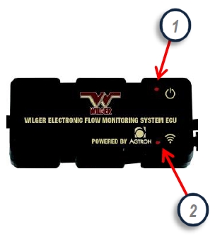
With the initial powerup of an ECU that has not yet had any connection to an Android tablet application, the ECU will cycle on 30 second intervals. It is NORMAL and functioning if the ECU power light stays solid for 30 seconds, with WIFI light blinking consistently, followed by both POWER/WIFI light turning off, and restarting the cycle.
POWER: SOLID RED // WIFI: BLINKING RED
30 Seconds, restart cycle until connection is verified.
If an ECU has not been connected to a tablet app, it will start this cycle to 10 seconds. (Power solid for 10 seconds. WIFI blinking for 10 seconds. Reset cycle)

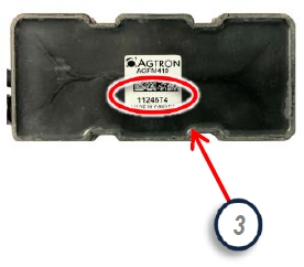
With the ECU, it generates a WIFI signal, the broadcasts on a WIFI channel. The WIFI channel used to broadcast on is hardcoded to the ECU, and is identified easily by the LAST NUMBER ON THE ECU SERIAL NUMBER.
For example: ECU Serial Number 1124674 would operate on WIFI CHANNEL 4.
If you are in the situation that you have been able to connect to the ECU during normal function, but it drops connection, you may need to verify if there is any conflicting communication hardware in the tractor/cab/implement that may be operating on the same WIFI channel.
With multiple signals on the same channel, it can cause interference causing dropping of signal.
Some example of other systems that might cause interference via WIFI channel:
-Tractor Monitor with WIFI signal through Router
-Seed blockage monitoring systems
-Auxiliary Systems that create a WIFI network for IoT (internet of things) connections
Some of these systems will have means to change WIFI channel from within their interfaces. If this is not the case, replacement of the equipment broadcasting hardware (e.g. EFM ECU) might be required.
If you are aware of existing WIFI equipment on the implement, ensure to specify a WIFI channel (or serial number digit) that will ensure clear communication.
For example, on the parts order from factory, specify: “ECU must NOT have serial number ending in ‘5’ ” if there was existing equipment operating on Channel 5.
The Wilger Electronic Flow Monitoring System has relatively low power requirement, but it must be met and accounted for on an implement to ensure proper operating.
Each system will require 1 AMP (ECU) + 0.25 AMP per node.
Example: For a system with 10 nodes, available power requirement would be 3.5 AMPs @ 12v. (1amp + 2.5amp)
The ECU is relatively simple in that it will always be searching out a WIFI connection, and despite going into a low draw mode, it will consistently draw electricity.
If the implement is not disconnected from battery during storage, it is recommended to have power linked through a keyswitch to ensure ECU is only receiving power when intended.
Since the EFM system requires power on the implement, there have been situations that the implement (e.g. planter, air drill) route power in strange ways, causing loss of power to the ECU.
One example of this that was difficult to troubleshoot:
- Tractor seemed to have proper application when standing still or sometimes in field application, but it would cut out without notice.
Result: Power to implement that was drawn to EFM system ECU was run through the brake light series, so it had power cut off whenever the brake lights were not active.
Ensure to check existing power and use a voltmeter that can determine that the required voltage is available to the ECU before suspecting a faulty ECU.
Within the flow monitoring system app, the app verifies proper connection to the ECU by means of matching the ECU serial number listed in the ECU settings page of the app.
If the ECU serial number in the app does not match, the ECU cannot connect to the app, and the system will not function.
Ensure all numbers are typed in properly, and there are no spaces or letters in the ECU serial number space (in the app).
NOTE: FOR ANDROID TABLETS USING ANDROID 10.0 or newer:
There is a new software function that is making itself available with authentication of connection to WIFI. The new update (as of Feb 2021) will not allow the EFM app authenticate with the WIFI signal from the ECU without the tablet first trusting the WIFI connection.
Having a WIFI connection to be trusted can be done by going into the SYSTEM APP on the android device.
Simply go to: SYSTEM -> CONNECTIONS -> WIFI – > Select the WIFI that is being broadcast by the ECU
ECU wifi will follow the following naming mechanism: WILGER_EFI_#######, with the ####### pertaining to the ECU serial number.
For example, for ECU serial # 1124674, the WIFI broadcast would be WILGER_EFI_1124674.
Whatever is listed as the trailing numbers following the WILGER_EFI_ would be the password for the WIFI signal.
First, ensure LOCATION SERVICES is set to ‘ON’. (To find LOCATION SERVICES: SETTINGS -> SECURITY -> LOCATION)
Within the flow monitoring system app, the app verifies proper connection to the ECU by means of matching the ECU serial number listed in the ECU settings page of the app. With Android 10.0 versions and newer, it changes how the initial connection to the ECU must be made.
To Determine your android device, enter the SETTINGS app -> ABOUT -> About Software. From there, you should see an Android Software version. Higher numbers are newer versions. The minimum android version for the EFM system is Android 8.0.
NOTE: FOR ANDROID TABLETS USING ANDROID 10.0 or newer:
There is a new software function that is making itself available with authentication of connection to WIFI. The new update (as of Feb 2021) will not allow the EFM app authenticate with the WIFI signal from the ECU without the tablet first trusting the WIFI connection.
Having a WIFI connection to be trusted can be done by going into the SYSTEM APP on the android device.
Simply go to: SYSTEM -> CONNECTIONS -> WIFI – > Select the WIFI that is being broadcast by the ECU
ECU wifi will follow the following naming mechanism: WILGER_EFI_#######, with the ####### pertaining to the ECU serial number.
For example, for ECU serial # 1124674, the WIFI broadcast would be WILGER_EFI_1124674.
Whatever is listed as the WILGER_EFI_####### would be the password for the WIFI signal. (Ensure to include the ‘WILGER_EFI_’ before the serial number)
NOTE: FOR ANDROID TABLETS USING ANDROID 10.0 or newer AND Wilger EFM app version 2.6.3 or greater.
With a new update of the Wilger WIFI Electronic Flow Monitoring System app (v2.6.3, released on Feb 22, 2021), a new prompt will start during setup, asking for permission to use the WILGER_EFI_####### wifi signal. This permission should be accepted for proper operation.
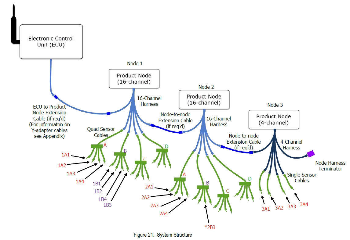
The flow monitoring system works with a daisy chained series of nodes and sensors, with a terminator(s) at the end of the daisy chain.
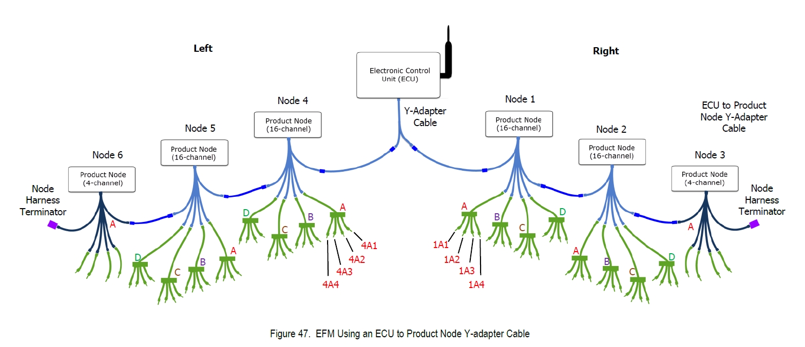
If a ECU splitter is used to split the chain to a left/right side of the implement, there will be a terminator required on both ends to close the loop.
- The first thing to check would be to ensure the terminators are fully snapped into the last node in the chain.
- The second would be to check that each node is connected to eachother, stemming from the ECU to the last nodes.
- For number of nodes, remember that the FIRST node connected to the ECU is Node #1. The ECU numbers the nodes based on connection to the ECU.
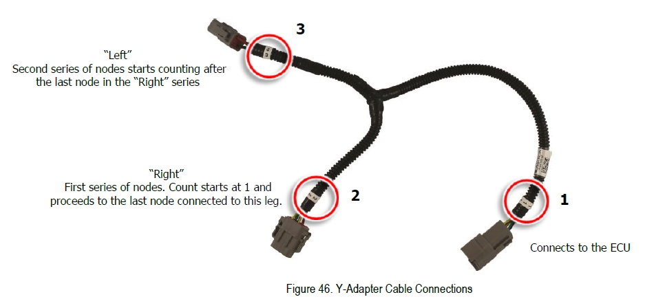
- In the event a ECU Splitter cable is used, the ECU will number the nodes based on the node chain stemming from the first cable outlet on the splitter (labeled with either B or 2), and will number nodes until the terminator is met.
- After the terminator is met, the ECU will resume number nodes from the splitter cable on the opposite side.
For example, for using a splitter cable (attached to the ECU) and 5 nodes on the right, and 4 nodes on the left:
- ECU will number the first to the right, from 1,2,3,4,5; then, it will resume the numbering on the left with the closest node to the ECU, with 6,7,8,9.
In the event that this is not understood, it can result in the app being set up incorrectly, and some sensors not being shown properly. Always verify sensors are entered correctly through initial setup. (with water running through the system, plugging off one outlet at a time and ensure it corresponds with the location within the app)
On the tablet, the app will alarm when there is a full blockage, or based on alarm threshold entered in app.
If the alarm is NOT sounding, it is common that the tablets volume has been muted. The alarm uses the devices volume setting, so it can be turned up or down to suit the operator.
If the alarm is sounding and is too loud, adjust the tablet volume. Alternatively, each SECTION on the main page can be muted individually (Sections 1-10) by pressing on the section button and HOLDING for 3 seconds. After 3 seconds, a prompt will pop up, giving option to mute the alarm for that section for a given time. (several minutes to half an hour).
Alternatively, the entire system can be muted by long-pressing the ALARM button in the bottom right of the screen when it appears, and selecting a mute length.
If a situation arises that you may have inputted the incorrect serial number in the app, or incorrect password in the WIFI authentication, you might try clearing the WIFI cache.
- Simply Turn Airplane Mode ON.
- While Airplane mode is on. Turn on WIFI and Location Services.
- Open the app, input ‘12345678’ in the ECU serial number slot (on ECU SETTINGS screen)
- Wait 2 minutes.
- Re-enter the correct ECU serial number.
Always ensure your ECU Antenna is mounted with good sight-line to the tractor cab to ensure best WIFI connectivity and signal. The standard 100′ Antenna (50′ one-way) is included in the ECU kit. If a replacement is needed, order part# 20603-03 for the Antenna Only.
If you require additional extension for the antenna to either get closer to the tractor, or to achieve proper sightlines, contact the Wilger factory for Antenna extension cable availability.
If the antenna is damaged or removed, it will greatly impact the WIFI connectivity and ability for the ECU to connect to the android tablet, so it is absolutely required for normal operation. Ensure the antenna connection is clean, free of debris, and installed in a location that would provide the clearest sightline to the tractor.

– If you see a blue lightning bolt on your main screen, DO NOT CONTINUE OPERATION. Unplug the ECU from power immediately and diagnose the cause.
This signifies there is a significant electrical problem which can cause hardware failure if not addressed. Hardware failure (harnesses, sensor cables, etc) can happen simultaneously with the blue lightning bolt picture.
– The blue lightning bolt dictate that the ECU is requiring too much power, signifying there is a problem in wiring or harnessing. Commonly, this may result from a shorted cable or harness, a bent connection pin, or variability in power availability from the tractor battery.
-To resolve this issue, you must identify the cause of the failure. This could include verifying appropriate voltage/amperage supplied to the system, checking for shorted/pinched cables.
– If shorted sensors are found, replace the flowmeter body itself, as the heat could melt the housing holding the sensor, causing subsequent failure (as solution will be able to enter the sensor area.
– Always ensure sensors are kept dry and away from corrosive fertilizers.

EFM TABLET SELECTION
Having a working tablet is just as important as having the EFM system set up correctly. Improper tablets or poor performing tablets can often be the root cause of many troubleshooting calls and issues, so to provide some explanation of what a ‘proper’ Android tablet would be:
Leading into this, there are over 30,000 android tablets that are ‘compatible’ with the EFM app, but tablet manufacturers do not make it very easy to tell actual differences in performance, or custom operating systems that are used on the tablet. So, this means we can give a general rule of which android tablet brands should be chosen, or what aspects of tablets should be avoided:
Suggested Tablet Brands:
Most brand-name tablets that are recognizable (Samsung, Acer, etc.)
Examples: Samsung Tab S9 or S10, Acer Iconia Tab P10 or P11
Tablet Brands/Types or Models to Avoid: (Often due to custom operating systems that are trimmed down or missing core functions, or have cheap WIFI hardware that will lead to poor performance or connectivity)
1. DO NOT USE Tablets with ‘LITE‘, ‘KIDS‘, or ‘+‘ in the name (Generally these tablets will be running a custom Android operating system, and often do NOT show that they are limited function tablets, not suitable for commercial use). For example: Avoid Samsung Tab S6 LITE, Samsung Tab A9+
2. DO NOT USE Phones are generally not to be used as they will also have mobile data being used, which can interfere with the sole WIFI function of the app. While phones can be used in airplane mode with WIFI on only to test systems or troubleshoot, it is recommended to use a tablet only.
3. DO NOT USE Amazon FIRE tablets – These tablets are a limited use tablet and not intended for commercial use. They are similar to a tablet with a custom operating system and trimmed down components that are not suitable for sustained commercial use. Often the apps will simply crash due to missing system components.
4. DO NOT USE very low-cost brands of tablets. Generally these tablets are very cheap (<$150), and have brand names that are unknown or not common at all. Sometimes these tablets have names or models that mimic a mainstream tablet, but are running non-standard or lacking hardware. (For example Linola Tab M9, UROA brand of tablets, ULTITAB, UNISOC, BLACKVIEW, BYYBUO, WPAD, TOPSAND, WEELIKEIT, ZTE, UMDIGI). Unfortunately, these non-branded or knock-off tablets are not suitable due to a variety of reasons. While they may work functionally somewhat, it is recommended not to use them as there will be software incompatibilities.
NODE & SENSOR Connectivity Issues & Observations
The sensors used in the Electronic Flow Monitoring Systems are hall-effect sensors, detecting changes in magnetic polarity. The hall-effect sensor mounted in the flowmeter body detects the polarity shift of the multi-pole ceramic magnet within the flowmeter body.
The hall-effect sensor transmits an analog pulse (ON/OFF) signal, or RPM that will be used to calculate the actual flow, using the appropriate color-coded JET. The color coded jets have a default calibration factor that is used to interpret the number of ‘pulses’ to the calibration factor, resulting in flow rate.
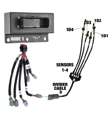
These sensors are located by the app based on the NODE # location (1-99), Divider letter on the node harness (A/B/C/D), and the molded-in Sensor number (1-4). From this location, the application will visually show that row where it would be on the implement, as well as the relative flow rate (based on average flow for the product).
So, a common situation on the first installation of a system is misunderstanding the sensor location relative to the ECU, which would result in the application showing feedback on the incorrect actual rows.
The ECU splitter cable can be used when it is required that the EFM system’s nodes are split across the wings of am implement, and not able to be centralized in manifold banks.
In this situation, the ECU dictates the label of a node (e.g. Node 1) by the FIRST connected node to the ECU Splitters label ‘2’ connector. The ECU will continue labeling nodes down the length of the daisy-chain until it reaches a terminator. After the terminator, the ECU will continue labeling nodes down the length of the daisy-chain until it reaches the terminator on the opposite side of the implement, starting with the ECU splitter label ‘3’ connector.
With the Electronic Flow Monitoring System, there is a 4 channel node available. It is available for when only 1-4 extra sensors are required. If there are 5 or more sensors required on an implement, it is typically cost effective to use 16-channel nodes instead.
Using 4 channel nodes is nearly identical to 16 channel nodes, and they can be freely mixed in with 16 channel nodes.
The main difference is that 4 channel nodes DO NOT have a DIVIDER Harness. So, when entering sensors within the application itself, and you are asked specify a DIV letter (A/B/C/D), if a 4CH node is used, it is always using DIV A. The only available options for a 4 Channel node are DIV A, and sensors 1-4 (based on labeled single sensor cables, which might also be labeled as TACH 1/TACH2/TACH 3/TACH 4 corresponding to their sensor #)
Electronic Flow Monitoring System Setup & Troubleshooting
The labeling scheme of sensors in an assemble EFM system is relatively straightforward, and it has been mentioned in some other of the FAQ articles.
There is also a video walkthrough for the EFM app setup. While some features of the app may have been added or changed, it is correct in process: https://www.wilger.net/video_efm_app/
Simply enough the EFM system app interprets PULSE signal from the sensors, tied to a specific location based on which node, divider harness, and sensor it used. So, if the 10th row on an implement is plugged into a sensor that is located on sensor 2, Divider C, and Node 1, when entering the location of that 10th outlet on the implement would be entered in the app as such:
NODE 1, DIV C, Sensor 2. It can then be labeled within the app as well, so the label of the outlet corresponds to the implements outlet.
The EFM system is completely able to monitor up to 3 products simultaneously, with shared electronic harnessing.
Exactly the same as how labeling sensors have locations based on the connection of the NODE/DIVIDER HARNESS/SENSOR, such do situations when multiple products are being monitored at the same time.
Simply enough, the products must only be seperated in PRODUCTS 1/2/3 within the app, with the sensors relating to those products entered accordingly.
So, if the 10th outlet for Product 1 (Liquid Starter Fertilizer) is plugged into one sensor, and the next sensor to it is the 10th outlet for Product 2 (28-0-0 fertilizer) as a seperate product, they might look like as follows:
Outlet 10 (PRODUCT 1): Node 1 DIV C Sensor 2
Outlet 10 (PRODUCT 2): Node 1 DIV C Sensor 3
Simply enough, those locations are still valid, and there will just have to be care to enter the two within the apps seperate product pages.
When entering sensor information within the app, using the Sensor Setup Page (wrench tool in upper right of the app), you might encounter two color diagnostics:
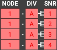
If a sensor outlet is highlighted RED; This indicates that sensor location has already been named, and is duplicated.
The duplicated entry must be found and removed. Ensure to check ALL products on ALL sections to find the duplicated entry.
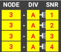
If a sensor outlet is highlighted YELLOW; This indicates that sensor location has named a NODE number that does not exist.
To fix this, enter the ECU Settings Page, and ensure the # of nodes is accurate to the implements layout. Also, ensure the Node is plugged into the EFM system communication harness daisy-chain, with a terminator at the last node in series.
In the event that upon setup of a system a ball/sensor on the main screen is showing as GREY, and located at the bottom of the product/section area, it indicates there is a communication fault with that sensor. This can be caused by a few things. While sensor failure is not common, it can be worth troubleshooting through the following checks:
If ONE sensor is grey, but sensors on the same quad-sensor cable seem to be working fine:
1. Unplug the troubled sensor and ensure no other sensors in the app go offline (or red). If another sensor went red, it was likely misslabeled within the app, and the troublesome sensor was located elsewhere.
2. Unplug the troubled one into the next flowmeter assembly and swap the sensors. Ensure both sensors are inserted in the correct orientation and threaded on fully, and cables are clear of any damage or pinching.
2a. If the problem follows the sensor, it can be determined something might be wrong with the sensor, or that the previous installation did not have the sensor in the correct keyed orientation or inserted deep enough.
2b. If the problem follows the EFM body, it could be missing the encoder magnet, or have debris within the sensor port that is causing interference.
If problem resolves itself and both are operating, ensure extra care that the both sensors are put in their correct flowmeters again, and install the sensors in proper orientation again.
If more than ONE sensor is grey, but some sensors on the same quad-sensor cable seem to be working fine:
1. Unplug the grey sensors on the implement. Ensure that no other sensors went RED or offline. Unplug the troubled one into the next flowmeter assembly and swap the sensor with one that was working properly. Ensure both sensors are inserted in the correct orientation and threaded on fully, and cables are clear of any damage or pinching.
1a. If the problem follows the sensor, it can be determined something might be wrong with the sensor, or that the previous installation did not have the sensor in the correct keyed orientation or inserted deep enough.
1b. If the problem follows the EFM body, it could be missing the encoder magnet, or have debris within the sensor port that is causing interference.
If problem resolves itself and both are operating, ensure extra care that the both sensors are put in their correct flowmeters again, and install the sensors in proper orientation again.
In the event that upon setup of a system a ball/sensor on the main screen is showing as GREY, and located at the bottom of the product/section area, it indicates there is a communication fault with that sensor. This can be caused by a few things. While sensor failure is not common, it can be worth troubleshooting through the following check:
If all sensors used on a quad-sensor cable are grey:
1. Unplug the grey sensors on the implement. If any other sensors on the app go RED, those sensors may have been mis-labeled, and the troubled quad-sensor cable or sensors are located elsewhere.
2. Take the troublesome quad-sensor cable and swap it with one on the implement that seems to be performing properly.
2a. If the troublesome quad-sensor cable does not work in the new position, inspect the quad-sensor cables for tears, breakage, pinched wires or other damage.
2b. If the troublesome quad-sensor cable DOES work in the new position, inspect the NODE harness that the troublesome quad-sensor cable was previously connected to.
-Use the good quad-sensor cable previously removed to verify if that was not just an insecure connection, by attaching it to the node and flowmeters and check if operation is restored.
-If operation was restored when a new quad-sensor cable was installed, try the troublesome one again, making special attention to the connections being secure and clear of liquids or dust, and ensuring pins on the connectors are straight and in good condition.
3. If it has been determined there may be a fault within the NODE harness, replace the node harness with a replacement, or simply replace it with a working node harness from another node. Verifying that the new harness fixes the error.
– NOTE: Any disconnected node harnesses should result in those node/sensor communications to go offline, so it is expected that those sensors are grey.


