


There are many reasons to consider replacing a sprayer boom. Most critical reasons to replacing boom piping might be of the following reasons:
- Replacing warped plastic boom pipe to stainless steel
- Replacing broken boom parts and improving the existing design
- Retro-fitting a sprayer to a recirculating plumbing system
- Replacing as much hose as possible with stainless steel feed pipe, to reduce chemical residue trapped in rubber hose
- Remove dead spots in the boom plumbing, reducing ability for chemical residue build-up
- Adding boom length to a sprayer’s existing swath
While all of these reasons can be important to invest the time and cost to retrofit a boom, there should be thought in getting the most of the retro-fit. Much of the extra benefits might be within the scope of the retro-fit, but must be planned for.
SCOPE of work: This would be if your sprayer boom is currently using a aged spray boom pipe (e.g. PVC tube that has warped), or converting from a dry-boom to a wet boom (hose plumbed boom to pipe-plumbed boom).
STEP 1: Make a sprayer boom layout based on existing sections or boom folds.
For example, if your sprayer is currently plumbed to have 7 sections that are center-fed on each section, for the simplest retrofit to stainless steel boom pipe, continue with the same nozzle layout by section.
An 120′ on 20″ spacing (~36m on 50cm) example layout might be similar to this (from left break-away section to right breakaway):

LEFT Breakaway: 5 outlet – sidefed
LEFT Secondary Wing: 11 outlet – centerfed
LEFT Primary Wing: 16 outlet – centerfed
Center Rack: 8 outlet – centerfed
RIGHT Primary Wing: 16 outlet – centerfed
RIGHT Secondary Wing: 11 outlet – centerfed
RIGHT Breakaway: 5 outlet – sidefed
Total of 72 outlets


For the center-fed pipes: we’d want to maintain 20″ spacing between the outlets, so the connection between the TEE must mirror that 20″ spacing as such. If the TEE fitting is 4″ from end to end, the pipes should be ordered with an 8″ end, such that the two pipes (8″ each) and the 4″ TEE, adding to 20″ between the outlets. On the pipe end that is NOT attached to the Tee, a simple ~2″ end would suffice. This would result in a 2″/8″ ended tube.
For side-fed pipes: as it is less critical to have any additional space off the end of boom pipe, we’d want to minimize the amount of space on each section. This would result in ~2″ ends on BOTH sides of the tube. This would result in a 2″/2″ end.
STEP 2: Cross-reference Nozzle outlets on each section to Wilger boom pipe part #, ensuring the ends are coordinated to fit properly with actual spacing.
An 120′ on 20″ spacing (~36m on 50cm) example layout might be similar to this (from left break-away section to right breakaway):
LEFT Breakaway: 5 outlet – sidefed – This would be a 5-Outlet tube with 2″ ends.
LEFT Secondary Wing: 11 outlet – centerfed – This would likely end up as a 5-Outlet & 6-Outlet tubes with 2″/8″ ends.
LEFT Primary Wing: 16 outlet – centerfed – This would likely end up as a 8-Outlet & 8-Outlet tubes with 2″/8″ ends.
Center Rack: 8 outlet – centerfed – This would likely end up as a 4-Outlet & 4-Outlet tubes with 2″/8″ ends.
RIGHT Primary Wing: 16 outlet – centerfed – This would likely end up as a 8-Outlet & 8-Outlet tubes with 2″/8″ ends.
RIGHT Secondary Wing: 11 outlet – centerfed – This would likely end up as a 6-Outlet & 5-Outlet tubes with 2″/8″ ends.
RIGHT Breakaway: 5 outlet – sidefed – This would be a 5-Outlet tube with 2″ ends.
Total of 72 outlets
With this, we can breakdown a parts list:
2x 5-Outlet 2″/2″ ends
2x 5-Outlet with 2″/8″ ends
2x 6-Outlet with 2″/8″ ends
4x 8-Outlet with 2″/8″ ends
Total tubes: 10 tubes
STEP 3: Compile Plumbing Connection Parts List
Depending on the style of fittings that are used (Quick-Nut fittings, or the newer Quick-Flange fittings), a variety of fittings would be required. In premise, these fittings will follow a similar format:
For Quick-Nut Fittings (QN100)
For any side-fed 2″/2″-end pipes (per pipe):
2x QN100 Male Pipe End Adapters (#25171-00)
2x QN100 Connection O-ring Seals (#25160-02)
1x QN100 Hose Barb or other feed fitting (e.g. 1-1/4″ 90° Hosebarb #25161-01)
1x QN100 Nut for each hose barb fitting or endcap, to bind the fitting to the Pipe-End Adapter (#25160-03)
1x QN100 End Cap or Boom End Flush Valve (e.g #25175-V0)
For any side-fed 2″/8″-end pipes (per pipe):
1x QN100 Male Pipe End Adapters (#25171-00) – for capped end
1x QN100 Female Pipe End Adapter (#25170-00 two-piece assembly) – For TEE fed end
2x QN100 O-ring Seals (#25160-02)
1x QN100 Tee type fitting* (e.g. QN100 x QN100 x 1-1/4″ Hosebarb TEE #25169-00)
1x QN100 End Cap (#25163-01) or Boom End Flush Valve (e.g #25175-V0)
Potentially required parts if End Cap is used instead of flush valve:
1x Additional QN 100 Nut (#25160-03) if an endcap (#25163-01) is used
*If a QN100-M x QN100-M x QN100 coupler Tee is used, additional o-ring, male end adapter,hose barb fitting, and nut would also be required.
For Quick-Flange Fittings (QF100)
For any side-fed 2″/2″-end pipes (per pipe):
2x Flange End Adapters (#27312-00)
2x 1″ SST Pipe to QF100 Seals (#27315-00)
2x QF100 Quick Clamp (#27310-00)
1x QF100 Hose Barb or other feed fitting (e.g. 1-1/4″ 90° Hosebarb #27343-00)
1x QF100 End Cap (#27353-00) or Boom End Flush Valve Assembly
For any side-fed 2″/8″-end pipes (per pipe):
2x Flange End Adapters (#27312-00)
2x 1″ SST Pipe to QF100 Seals (#27315-00)
2x QF100 Quick Clamp (#27310-00)
1x QF100 TEE feed fitting* (e.g. QF100 x QF100 x 1-1/4″ Hosebarb TEE #27322-00)
1x QF100 End Cap (#27353-00) or Boom End Flush Valve Assembly
Potentially required parts if End Cap is used instead of flush valve:
Replace 1x 27353-00 with a #27351-00 (end thread adapter x flange), Flush Valve (#25175-LV0), and flush valve seal (#25160-02)
*If a QF100 x QF100 x QF100 Tee is used, additional QF100 to QF100 gasket (#27317-00), Quick Clamp (#27310-00), and hose barb fitting (e.g. 90° 1-1/4″ Hose Barb – #27343-00) would be required.
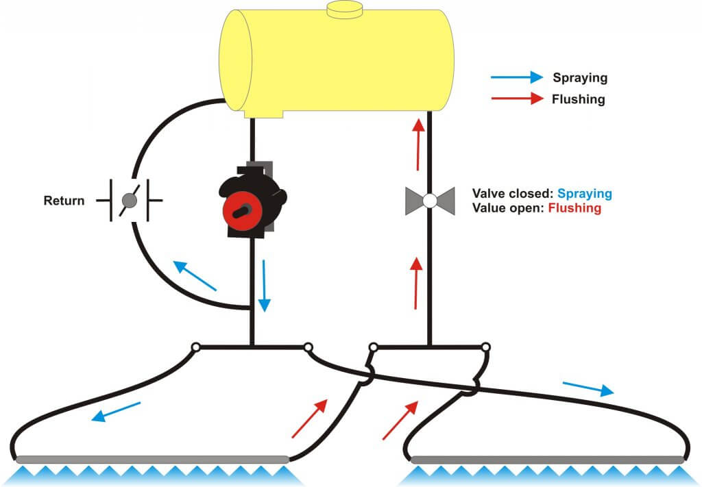
SCOPE of work: This would be if your sprayer boom is currently conventionally plumbed by section, and you have some means to turn off nozzles remotely in the cab during recirculating mode (e.g. PWM system, air-off nozzle control, etc). The walkthrough will ONLY address how the plumbing on the boom would change, not the feed lines/return lines as there are a number of ways to vary feed. Perhaps consult the ‘recirculating boom guide’ at Sprayers 101 (https://sprayers101.com/recirculating-boom/) for some insight.
STEP 1: Decide on plumbing orientation for flow inflow and recirc outflow.
Example configurations:
“Outside IN”: Plumb main boom feeds to feed from both outside wings (or breakaway sections), with the recirculating outflow leading back from a common center-rack outflow.
“Inside OUT”: Plumb two feeds from center rack to supply right boom and left boom, with the outflow of the sprayer boom continuing from the right and left outside boom connecting back to a single outflow when the meet at the center rack.
Recirc Tube versus Hose Option: Regardless of orientation, you might also choose to replace the plumbing hoses on the sections with unpunched stainless steel tubing to have less plumbing weight (compared to 1-1/4″ rubber hose), as well as maintain easier to maintain sprayer booms for chemical buildup.
STEP 2: Cross-reference Nozzle outlets on each section to Wilger boom pipe part #, ensuring the ends are coordinated to fit properly with actual spacing.
Since recirculating booms require consistent nozzle spacing to be kept, boom ends can be as short as possible to minimize sharp elbow fittings and boom frame interference. This means any connectors could be 90°/45°/Straight hose barb fittings with ~2″ ends. For very long tube sections, (e.g. more than 11-nozzle tubes/pipes) expect to have those sections plumbed by multiple tubes with a 2″ end/10″ end to ensure 20″ spacing it kept between ‘tube to tube’ connections.
PRO TIP: If spray boom tubes are being shipped, it is common to try keep tubes shorter than 11′ to avoid ‘extra long package’ charges from some carriers/shipping companies.
An 120′ on 20″ spacing (~36m on 50cm) example layout might be similar to this (from left break-away section to right breakaway):
LEFT Breakaway: 5 outlet – sidefed – This would be a 5-Outlet tube with 2″ ends.
LEFT Secondary Wing: 11 outlet – sidefed- This could be an 11 outlet single tube, with 2″ ends.
LEFT Primary Wing: 16 outlet – sidefed – Given this tube’s length, it would likely be split into 2x 8-outlet tubes, with 2″ and 10″ ends. (The 10″ end would be the tube to tube connection)
Center Rack: 8 outlet – sidefed- This would likely end up as a 4-Outlet & 4-Outlet tubes with 2″/2″ ends. This would allow for the two tubes to have a 90° elbow that feeds back to the tank (or is fed from pump, depending on chosen orientation).
RIGHT Primary Wing: 16 outlet – sidefed- Given this tube’s length, it would likely be split into 2x 8-outlet tubes, with 2″ and 10″ ends. (The 10″ end would be the tube to tube connection)
RIGHT Secondary Wing: 11 outlet – sidefed- This could be an 11 outlet single tube, with 2″ ends. Alternatively, it could be something like an 8-outlet tube with 2″ end/10″ end as well as a 3-outlet with 2″/10″ end. The benefit for a 8+3 tube situation is reducing the shipping length to the minimum acceptable size, and having common tube parts.
RIGHT Breakaway: 5 outlet – sidefed – This would be a 5-Outlet tube with 2″ ends.
Total of 72 outlets
With this, we can breakdown a parts list:
2x 5-Outlet 2″/2″ ends
2x 11-Outlet with 2″/2″ ends
2x 4-Outlet with 2″/2″ ends
4x 8-Outlet with 2″/10″ ends
Total tubes: 10 tubes
STEP 3: Compile Plumbing Connection Parts List
Depending on the style of fittings that are used (Quick-Nut fittings, or the newer Quick-Flange fittings), a variety of fittings would be required. In premise, these fittings will follow a similar format:
For Quick-Nut Fittings (QN100)
For any side-fed 2″/2″-end pipes (per pipe):
2x QN100 Male Pipe End Adapters (#25171-00)
2x QN100 Connection O-ring Seals (#25160-02)
2x QN100 Hose Barb or other feed fitting (e.g. 1-1/4″ 90° Hosebarb #25161-01)
2x QN100 Nut for each hose barb fitting or endcap, to bind the fitting to the Pipe-End Adapter (#25160-03)
For any PAIR of side-fed 2″/10″-end pipes (per PAIR of pipes):
3x QN100 Male Pipe End Adapters (#25171-00) – 2x for capped end, 1 for tube to tube connection.
1x QN100 Female Pipe End Adapter (#25170-00 two-piece assembly) – For Tube to tube connection
3x QN100 O-ring Seals (#25160-02)
2x QN100 Hosebarb Outlets (#25161-01 for 90° 1-1/4″ elbow on either side)
2x QN100 Nuts (#25160-03 for connecting hosebarb fittings to pipe end adapters)
For Quick-Flange Fittings (QF100)
For any side-fed 2″/2″-end pipes (per pipe):
2x Flange End Adapters (#27312-00)
2x 1″ SST Pipe to QF100 Seals (#27315-00)
2x QF100 Quick Clamp (#27310-00)
1x QF100 Hose Barb or other feed fitting (e.g. 1-1/4″ 90° Hosebarb #27343-00)
1x QF100 End Cap (#27353-00) or Boom End Flush Valve Assembly
For any PAIR of side-fed 2″/10″-end pipes (per pair of pipes):
4x QF100 Male Pipe End Adapters (#27312-00)
1x QF100 SST tube to SST tube gasket seal (#27318-00)
2x QF100 SST to Flange Gasket Seal (#27315-00)
3x QF100 Clamp (#27310-00)
2x QF100 Hose Barb or other feed fitting (eg. 1-1/4″ 90° Hosebarb #27343-00)
SCOPE of work: This would be if you intend to retro-fit or adjust a sprayer boom to have cleaner sprayer boom hygiene, ensuring there is passive air purge (to alleviate nozzle run-on) and less dead-space for any chemical build-up.
There might be a few ways to go about this, from most intensive to easiest to accomplish with minimal cost.
Most Intensive: Replacing the current spray boom tube with new tubing, replacing it with a custom spray boom with short ends that incorporate the last nozzle body into the endcap of the sprayer boom. This would be using the Quick-Flange sprayer fittings with a boom end flush valve built into the last nozzle body on each boom pipe. (Combo-Rate Boom End Flush Valve is available Fall 2021)
This would ensure the last nozzle body is flushed at the exact position of the last nozzle body, leaving no dead space within the sprayer boom. With this valve (‘CR BEFV’), it also merits having the last nozzle body situated that it passive purges the air out of the boom without any additional moving parts, small components, or other designs that might inhibit air purging at low water rates or pressures.
Least Intensive: To reduce air trapped in the sprayer boom, another means to retrofitting a sprayer to remove this would be to rotate the existing sprayer boom180° such that the nozzle body inlets are point upwards. Then, using a Combo-Rate II saddle body (e.g. Two-way 41475-00 saddle) attaching a stack nozzle body or turret will have every single nozzle body pulling air directly out of the sprayer boom first, so there is no air in the sprayer boom at all.
For flushing & cleaning purposes, the entire bottom of the sprayer tube is now solid, so sprayer flushes will be less inhibited by nozzle inlets and catch points, and allows the operator to use other means to maintain sprayer boom hygiene with an interior pipe cleaner.
SCOPE of work: This would be removing as much hose as possible down the sprayer’s boom, replacing it with rigid stainless steel tubing.
This would encompass replacing the existing hose down the length of the sprayer to a low-weight stainless steel tubing (like Wilger’s SST) for a few main benefits:
- Sprayer Boom Hygiene & Chemical residue deposits – Hose is a culprit to entrapping chemical residues, especially hose that is maintaining all the bends that a sprayer requires for plumbing each nozzle section.
- Replacing the lengths of hose that follow the profile of a sprayer boom with stainless will allow for better boom hygiene (as you can much easier clean, and the smooth surface doesn’t catch any residue in cracks that develop overtime)
- Having each of the plumbing sections plumbed with fittings that remove much of the hose bends will ensure better flow distribution compared to large bends of hose. Those bends of hose will also develop cracks with use that are culprits in holding chemical residue/rinsate until the next time the sprayer is pressured up.
- Reduction in Weight – Given the swath of a sprayer (often over 135′ feet now), any reduction in boom weight can greatly impact the sprayer booth in responsiveness of boom movement, and minimize sprayer wear and tear of boom frame joints and structure.
- Since Wilger Stainless Steel Tubing is lighter than physical plumbing hose, it becomes a great means to lessen weight on the sprayer boom and have better rigid joints connected to the boom frame itself.
- For sprayer fuel use, reducing sprayer weight pays dividends is reduced fuel usage as well, ensuring there is a consistent and measurable payback on such a retrofit.
- Aesthetics & resale – Especially in situations where resale might be in the near feature, having a dual stainless boom would prove to differentiate a sprayer ensuring a premium price of sprayer. With the stainless plumbing, it also opens up a great deal of options for sprayer system modifications to transition to a recirculating boom with stainless return plumbing.
Overall, Wilger’s stainless steel tubing has the internal flow capacity of 1-1/4″ tubing size with the exterior profile of 1″ pipe (1.315″ OD), so it becomes a very clean way of plumbing a sprayer to not only make it look better but have it cleaner and more functional in-season as well.
SCOPE of work: This would be extending an existing sprayer boom (e.g. 120′) to a longer length, but adding a sprayer boom to the outside of the existing boom frame (e.g. expanding it to 132′ by adding 6′ of length to both sides of the sprayer). There can be a number of reasons for these kind of additions, such as reducing the last pass in fields, increased productivity, matching planting equipment spacing/widths.
In many ways, this is one of the simplest additions to a sprayer in initial concept, as it would be adding on a length of spray boom to the outside section (or breakaway). While the Wilger spray boom fittings are simple (as you are simply adding additional nozzle bodies), there are some things to consider when adding sprayer boom length:
- Interference with existing sprayer boom and folding – Ensure everything will actually fit when folded and your existing sprayer has sufficient room to actually add the length.
- Sectional Control – Ensure you have an understanding of where and how that new addition is being fed, and ensure you are able to make the adjustments in your sprayer monitor to adjust for that section size.
- Sprayer Weight – While it doesn’t seem like much, ensure any additions to the frame are sufficient for serious wear and tear. Bear in mind the sprayers frame could now have the equivalent of hundreds of pounds of extra weight on a 60′ wing of a 120′ sprayer, depending on whether both sides of the sprayer are keeping equal balance well.
- ‘Break-away’ action – OEM sprayers typically have means to have sufficient damage control of an accidental contact of the sprayer boom. With this, there are complexities, as the breakaway section must be freely able to kick back in the event of accidental serious contact, BUT it also must remain rigid and in position during regular spraying use. There might be a requirement of tension springs, hydraulic dampers or air bags to ensure the new extension is functioning properly, but also the pre-existing outside section is still able to operate with the extra weight and drag caused by it.
- Some situations might allow a rigid addition to the existing breakaway section, but function of the existing breakaway must be paid attention to, as they have not been designed to support additional fixed weight off the sprayer boom.
There are just some of the considerations that must be addressed during this sort of retrofit. While the plumbing parts are likely the easiest part of it, there are some repercussions if they are not considered and addressed.
SCOPE of work: This would be adding an additionally plumbed sprayer boom onto an existing sprayer to function as a spot-spraying system. These systems are often used independently of a broadcast spraying boom, and in many situations benefit from having a separate standalone boom to manage different chemicals/mode of actions/etc that might not be used in broadcast sprays.
In this situation, it would include plumbing a custom spray boom on narrow nozzle spacing (eg. 6-10″ outlets instead of 20″ spacing). Aside from a great deal of planning for the sprayer boom, it would mirror adding a new sprayer boom tube (see “Retrofitting a sprayer to stainless from plastic/pvc guide” for example).
Aside from physically plumbing the sprayer, there are some considerations:
- Narrow spacing can introduce many ‘pinch points’ on your sprayer frame. Depending on how your sprayer frame is built, having the sprayer boom inside a boom frame might not be an option with 8″ spacing, so either expect to mount it outside of the boom frame, or be prepared to build ‘remote sections’ outside of the boom frame for areas that have unavoidable pinch points.
- Sprayer/Boom Weight – Adding a dual boom can introduce a lot of weight, not only the boom tube and plumbing, but also the consideration for the liquid-filled tube weight. Depending on flow requirements and intended use, this might be a situation to consider using Quick-Nut 50 series 1/2″ stainless steel tubing, which flows equivalent to a 3/4″ pipe. The reduction in ID size would mean there is less weight down the length of the sprayer boom.
- Nozzle Size – A reduction in narrow-angle spray nozzles will mean you are using dramatically smaller nozzles that you might be used to. Overall, your nozzle size would be less than half the size of what you are using. (as you would be transitioning from 20″ spacing to 6-10″). This might limit the types of nozzles and drift reduction options that are available, so ensure you take a look at what Wilger has for Combo-Jet DX series of nozzles for spot spraying to ensure the size required is available.